


Carbide Cutting Tools: Wear, Speed and Cryogenic Treatment
Carbide tool life exceeded 40 minutes at 100 metres per minute or below in a University of Birmingham study by Hood and colleagues (2018), using a 200 micrometre flank-wear limit. Its steep tool-life curves make the practical point: establish a stable speed window before testing cryogenic treatment. A harder-working edge isn't necessarily a longer-lasting one.
Table of Contents
What Carbide Cutting Tools Are Made Of
A typical carbide cutting tool has a hard edge made from tungsten carbide grains bonded with cobalt. Grains are the hard particles; the binder is the metal holding them together; toughness means resistance to chipping.
Think of gravel set in concrete. The carbide grains resist abrasive wear, while the binder supports them and accommodates some loading. Choose solely for hardness and an interrupted cut can expose the weakness: an edge that resists rubbing but chips under impact.
A University of Warwick thesis by Wilkinson (1992) records that, by 1933, cemented carbide could cut mild steel at about 250 metres per minute, against about 80 metres per minute for high-speed steel, roughly 3.1 times faster. Early tools nevertheless attracted criticism for brittleness and chipping.
The thesis identifies four families: tungsten carbide with cobalt, cemented titanium carbides, mixed cemented carbides and coated carbides. For a product-oriented explanation alongside that materials background, EZARC Tools describes its carbide technology for cutting tools.
The grain-and-binder arrangement explains the basic trade-off.
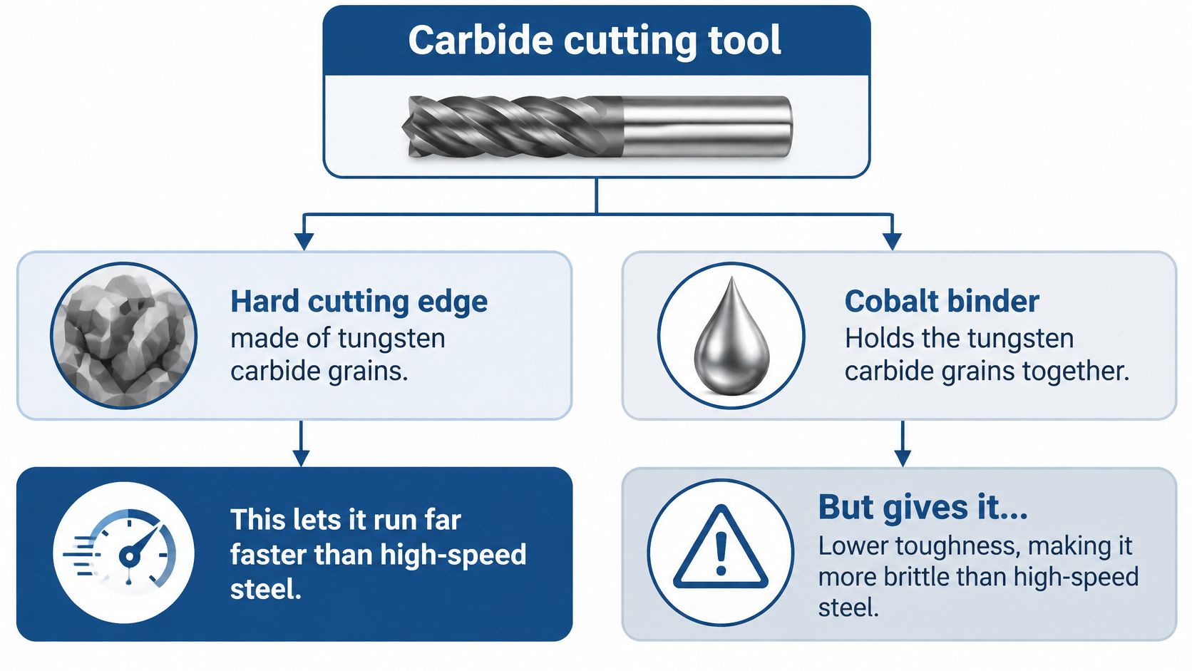
Choose the grade for the operation, not for the highest available hardness.
Cutting Speed Limits by Tool and Work Material
Reference cutting speeds by tool and work material
Tool and work material | Reference cutting speed | Source and context |
|---|---|---|
High-speed steel tool, mild steel | Up to about 80 metres per minute | Historical maximum in Wilkinson's Warwick thesis |
Cemented carbide, mild steel | About 250 metres per minute | Same thesis, historical performance milestone |
Cemented carbide, wrought Ti-6Al-4V | 30 to 60 metres per minute | Conservative range reported in the University of Leeds paper |
PCD milling, Ti-6Al-4V | 500 metres per minute | Same Leeds paper, with feed reduced to maintain acceptable wear |
Cemented carbide, nickel-based superalloys | Below 60 metres per minute | University of Birmingham aerospace machining thesis, even with high-pressure coolant |
PCBN, nickel-based superalloys | Substantially faster than carbide | Same thesis; tool life can be shorter |
Carbide, difficult material in Birmingham study | Tool life over 40 minutes at 100 metres per minute or below | Hood and colleagues, with a 200 micrometre flank-wear limit |
These are orientation values from separate studies, not a like-for-like comparison or a machining programme. The historical mild-steel figures aren't settings for titanium.
PCD means polycrystalline diamond. PCBN means polycrystalline cubic boron nitride, a different tool material with its own operating window.
Flank wear is the worn band on the tool's clearance face. A Taylor tool-life curve plots tool life against cutting speed; a steep curve warns that a small speed increase can sharply shorten usable edge life.
Practical rule: Measure flank wear, finish and cutting force at several speeds. Choose the highest speed that still meets your tool-life target.
For our machining treatment service, that measured operating window is the starting point for a useful comparison, not something treatment replaces.
Wear Modes, Their Causes and Fixes
A flank-wear band tells a different story from a missing corner. Inspect the edge under magnification before changing the grade or booking treatment.
Carbide wear symptoms, causes and first checks
Symptom | Likely cause | Check or change first |
|---|---|---|
Flank wear band on the clearance face | Abrasion, aggravated by demanding cutting conditions | Reduce speed first; check feed, depth and grade suitability |
Rounded cutting edge | Progressive abrasive dulling | Track edge radius between cuts; trial a lower speed |
Built-up material and poor finish in titanium | Adhesion and material transfer | Check coolant and coating; inspect build-up without damaging the edge |
Chipping or sudden fracture | Excessive mechanical and thermal loading | Check rigidity, entry conditions and grade toughness before increasing speed |
A University of Birmingham study of tungsten-carbide cutters trimming carbon-fibre-reinforced polymer found abrasive grain wear and edge rounding, with life decreasing as cutting speed, feed speed and depth increased. Its wear model predicted measured wear with an approximate average error of 5%.
That doesn't make abrasion the explanation for every failed edge. A University of Greenwich investigation of dry Ti6Al4V machining identified strong adhesion and material transfer as major contributors to uncoated-carbide wear.
For each suspected mechanism, compare matched edges at your current speed and a reduced speed, holding other settings fixed. Photograph the same edge locations rather than judging by appearance from memory.
Record time in cut, wear-band width and surface finish whenever a tool comes out. Record sudden breakage separately from progressive wear.
Choosing the Right Coating and Coolant
A PVD multilayer based on TiN/TiAlN, titanium nitride and titanium aluminium nitride, outperformed CVD-coated and uncoated carbide during dry Nimonic C-263 machining in a study available through Teesside University. It reduced cutting temperature, surface roughness, cutting force, chip-reduction coefficient and average flank wear.
PVD means physical vapour deposition; CVD means chemical vapour deposition. MQL, minimum-quantity lubrication, supplies a small lubricant quantity, commonly as an oil mist.
These are different categories: PVD and CVD describe coating processes; MQL describes lubrication.
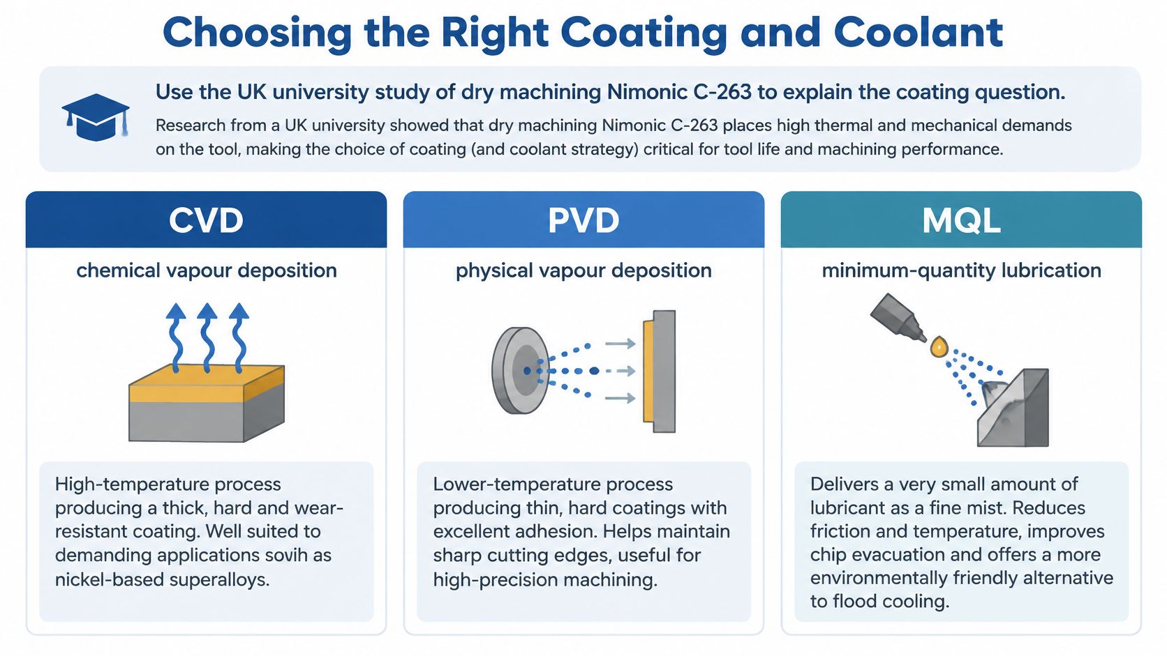
In the same study, uncoated carbide performed better with MQL or flood coolant than CVD-coated carbide, although it remained below the PVD tool. Coating and cutting environment interact.
Match the application. Select a coating family for the work material and your actual coolant arrangement.
Isolate the change. Don't change coating and cutting speed together.
Hold the comparison steady. Keep coolant delivery, feed and depth fixed when comparing inserts.
A dry-cutting winner isn't automatically the flood-coolant winner. Test at a wear-validated speed using the coolant your shop runs day to day.
What Cryogenic Treatment Does to Carbide Tools
We cool parts slowly to around minus 196°C in nitrogen gas, hold them, then return them slowly to room temperature through a computer-controlled cycle taking about three days. Parts never touch liquid nitrogen.
The diagram outlines the process rather than a guaranteed performance result.
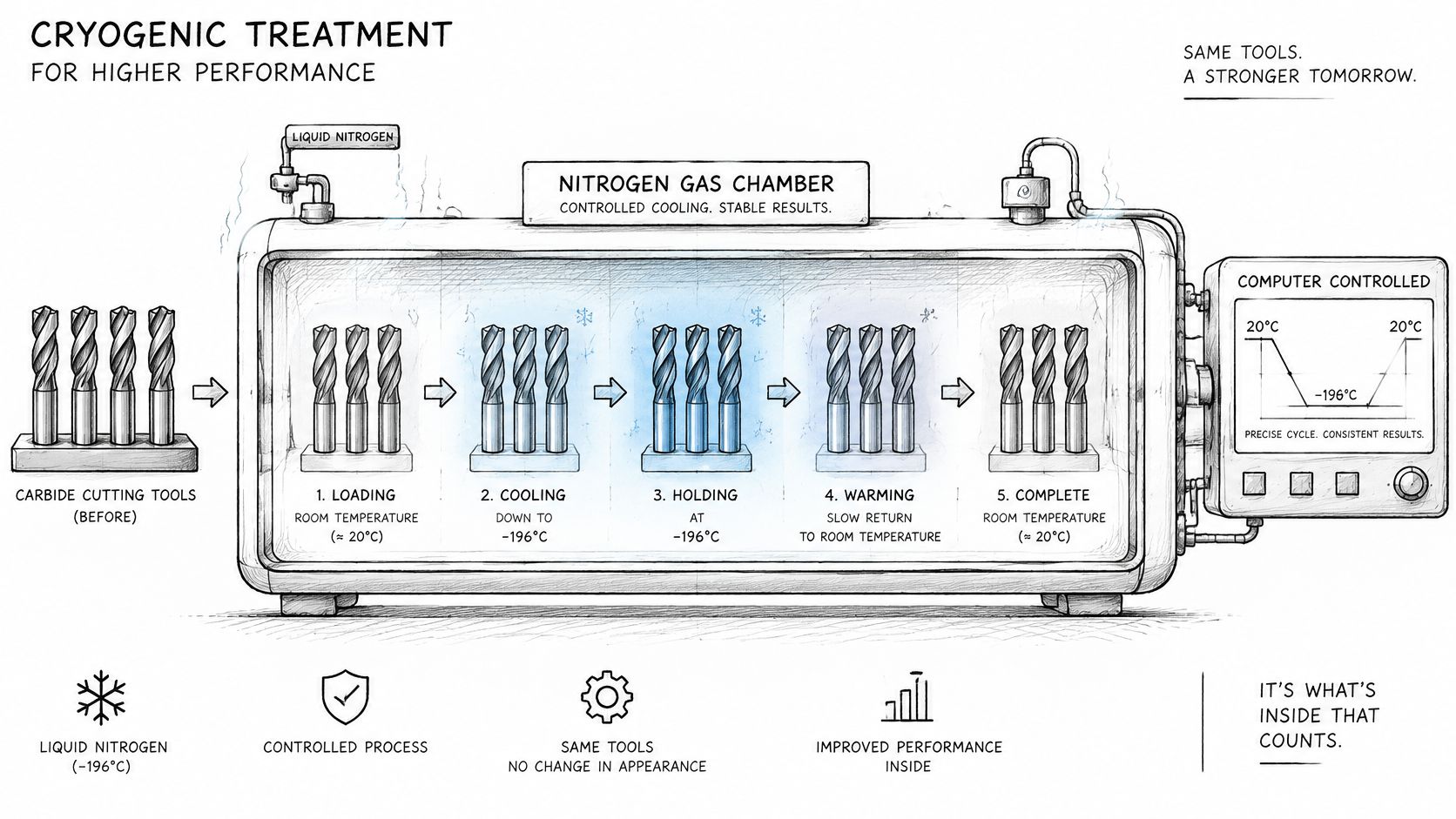
Published evidence is stronger for tool steels than for cemented carbide. In steels, retained austenite, an austenitic structure remaining after hardening, can convert to martensite, a harder structure, and fine carbides form. Don't transfer that explanation unchanged to tungsten-carbide grains in a cobalt binder; carbide-specific mechanisms remain less settled.
Evidence for cryogenic treatment by tool material
Tool material | Published research | Cryogenix experience |
|---|---|---|
Tool steels, including drills and end mills | Reviews describe wear gains in many steels; results vary widely | We treat drills and end mills; application affects results |
High-speed and martensitic steels | Transformation and carbide formation are relevant mechanisms | Results vary by material, prior heat treatment and application |
Cemented carbide tips and band saw blades | Carbide-specific evidence is limited; blade construction must be identified | We treat carbide tips and band saw blades; no gain is guaranteed |
In our experience, treated cutting tools can achieve many-fold increases in productive life, retain sharpness and become less prone to failure. That's our experience across cutting tools, not a carbide-specific research result, and results vary by material, prior heat treatment and application.
We normally recommend treatment after machining because machining introduces stresses. For many steels, it complements conventional heat treatment rather than replacing it.
Our sub-zero treatment overview provides further context. This video accompanies the process explanation.
When Cryogenic Treatment Will Not Help
A chipped, cracked or broken tool won't be repaired by cryogenic treatment. Regrind a salvageable tool or replace an unsafe one before considering any treatment trial.
Excessive speed is another poor starting point. Stabilise speed, feed and depth first, otherwise rapid wear can overwhelm any potential benefit and leave you unable to interpret the result.
Treatment isn't a substitute for a rigid setup, suitable geometry or reliable coolant delivery.
Adhesion during dry titanium machining calls for a coolant and coating check. An edge that chips shortly after entering the work calls for inspection of clamping, overhang and engagement, followed by a reduced-speed comparison.
Treatment may also be uneconomic for inexpensive tools replaced on a fixed schedule without a wear problem. Compare treatment and handling costs with avoided purchases, tool changes and rejected components, not merely the purchase price of an insert.
We don't guarantee a gain. Results vary by material, prior heat treatment and application, and without measured untreated and treated life, you can't tell whether treatment helped.
How to Test Treatment Against Your Own Baseline
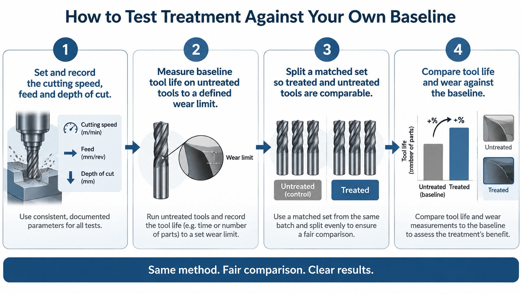
A matched pair of tools tells you more than a single long-lived edge ever will. One treated insert run beside an untreated twin, on the same programme and the same coolant, gives you a number you can act on. Published research on cemented carbide is thinner than on tool steels, so your own side-by-side result carries real weight here.
Record cutting speed, feed and depth so the programme is repeatable.
Measure untreated life to a defined wear limit, not just until the tool breaks.
Split a matched set with identical grade, geometry and coating.
Treat one half and retain the other as untreated controls.
Run both under identical coolant and workholding conditions to the same limit.
Record life, finish and cost per accepted component, including tool-change time.
Decide from those measurements rather than the longest-lasting individual edge.
Identify every tool and edge before dispatch. Don't torque assemblies together; lightly oil corrosion-prone ferrous parts and remove pressed-in bearings where possible.
Single items are accepted and run in the chamber alongside other customers' parts on the next scheduled run, so check the next processing date and the step-by-step process guide when planning your trial window.
Returned parts come back dimensionally unchanged and visually identical, with no added surface layer, which is why identification records matter once treated and control tools share a drawer. If a treated edge still fails early through chipping rather than gradual flank wear, repeat the comparison at reduced speed before counting that result.
Common Questions About Treating Carbide Tools
Does treatment stop flank wear?
No wear reduction is guaranteed. Published research covers tool steels far more thoroughly than cemented carbide, and Cryogenix's reported gains, such as a pallet manufacturer's band saw blades lasting two weeks instead of four days, still leave your carbide grade unproven. Results vary by material and application, so run a treated edge against an untreated control at the same cutting speed, to the same wear limit, before expecting an improvement.
Does treatment survive regrinding?
Treatment adds no coating or surface layer, so there is nothing to peel or wear away. Whether any effect on a carbide tool remains after regrinding depends on the material and application. Measure the reground edge against your baseline rather than assuming the benefit carries through.
Will a chipped carbide tool come back usable?
No. Treatment does not repair damage, and a chipped edge stays chipped. I would regrind first if the geometry allows, since in most cases treatment is best carried out after machining, which introduces stresses of its own. Judge the tool afterward on edge life and finish.
Does treatment change tool size?
No. Parts come back dimensionally unchanged and visually identical, with no coating, plating or added layer. Mark treated and untreated tools clearly before dispatch, because nothing about their appearance will tell them apart later.
References for the cryogenic evidence
Baldissera and Delprete (2008), Deep cryogenic treatment: a bibliographic review, The Open Mechanical Engineering Journal.
Podgornik and others (2016), Deep cryogenic treatment of tool steels, Journal of Materials Processing Technology 229.
Jurči and Dlouhý (2024), Cryogenic Treatment of Martensitic Steels.
Cryogenix, academic research library.
We offer deep cryogenic treatment for carbide tips and other cutting tools, with single items accepted for a controlled workshop trial. Visit Cryogenix Ltd, record each tool's weight and edge condition, and ask for a quote at info@cryogenix-uk.com or through our contact page. Check the next processing date before dispatch.
Comments